In the molding cycle of plastic parts, the cooling time accounts for about 70%-80% of the whole molding cycle. A well-designed cooling system design can reduce product warpage deformation and cycle time. Therefore, the design of the cooling channel is the most important that will affect cooling efficiency, production efficiency and cost control. To obtain uniform cooling efficiency, Moldex3D provides a Cooling Analysis module and tools for users to design and optimize the cooling channel. Moreover, Conformal Cooling Wizard enable users to quickly create a cooling channel design that fits the product geometry and into hard-to-reach areas. Moldex3D Conformal Cooling Wizard has further enhanced for better creating the conformal cooling system. Users only need to define the 2D channel curve, and the wizard will quickly create the Conformal Cooling Channel mapping on the part shape. The optimized cooling channel can then improve the heat dissipation of the cooling efficiency and product quality and shorten cooling time.
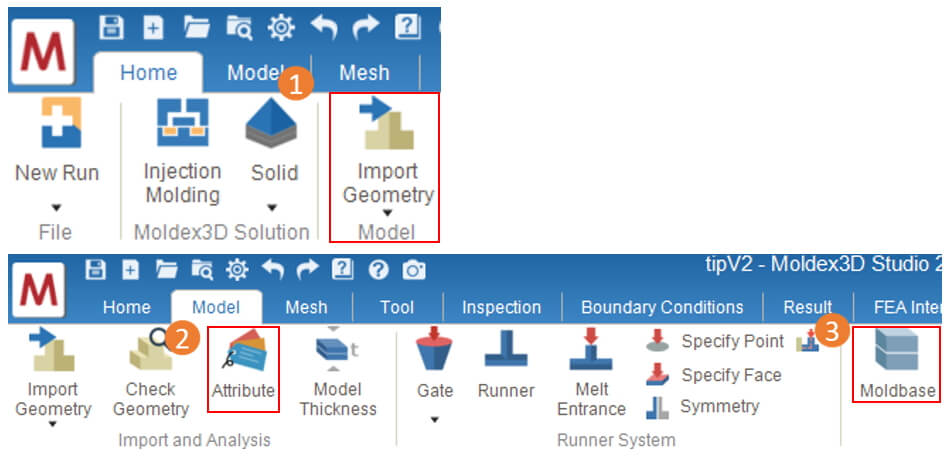
Step 1. Import Geometry
Create a new Injection Molding project and select the Mesh Type as Solid. Use wizard tools or other functions, such as Import Geometry and Attribute to create model objects until there include Parts and Moldbase in the model.
Note:
- Shell models and models in MFE file are not supported; Please ceate a Moldbase before using the Conformal Cooling
- To ensure a good aspect ratio, it is necessary to create a surface mesh on the part. Please avoid directly using the CAD data from STL files.
Step 2. Create the Conformal Cooling Channel
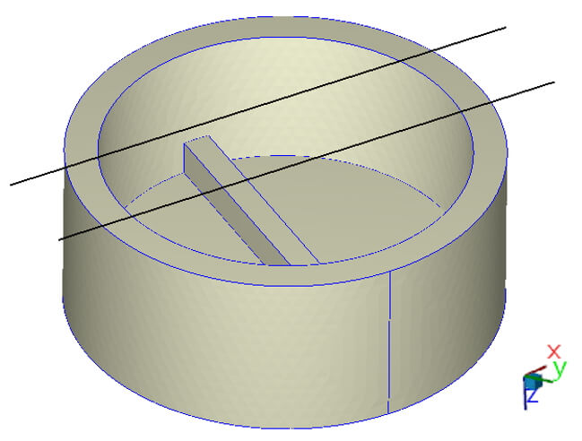
2-1 Draw 2D layout with curves
Prepare the 2D channel curve or use the point / line tools in the †Tool Tab †to draw the channel curve over the Part.
Note :
- The drawn curves must be continuous and on the same plane for each cooling channel, excluding ï¼›the inlet and outlet part can be set in different axial directions.
- For on-site application, the curves for each cooling channel should not be too complex or across mold opening face, although this is allowed in Studio.
- All curves can’t be intersected with the part.
- For overall 2D layout, the start and end point should exceed the product projecting area.
- Avoid undercut structures of the part is recommended to prevent failures.
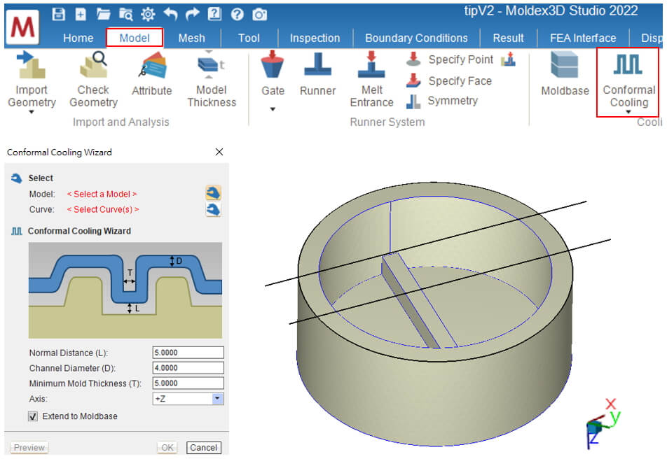
2-2 Create the Conformal Cooling Channel
In †Model Tab “, click the †Conformal Cooling Wizard †and select Part and the 2D layout curves, set the parameters according to the product geometry, click †OK †after completion. The 2D curve will be projected onto the product surface and create conformal cooling channels.
Note: The parameters in the wizard will affect how the cooling channel is close to the product and some small features. Although the efficiency is better when the cooling channel is closer to the part, the actual tooling processability and the quality of mesh generation should be considered when setting parameters. Please check the cooling channel design at least meet the following:
- Normal vector distance (L) should be enough distance between part and cooling channels.
- Cooling channel diameter (D) must meet cooling channel design rules. (Cooling Channel Wizard >> Guide or use own rules)
- Minimum mold thickness (T) should avoid creating too thin area in moldbase.
- The axial setting should match with cooling channel layout direction.
Step 3. Â Complete the mesh and analysis settings
After completing conformal cooling channel design, click on †Inlet/Outlet †to set the water inlet and outlet. Finally, click on †Check Cooling System †to complete the cooling system design. Then, prepare a solid mesh on the †Mesh Tab †and click on †Final Check “. Once done, finish process condition and other analysis setting and submit the analysis job for calculation. Be sure to include cooling in analysis sequence, and the cooling results can then be checked as calculation done.
(Users can enable Cooling Channel Analysis or other advanced settings in Computation Parameter to achieve better simulation results).

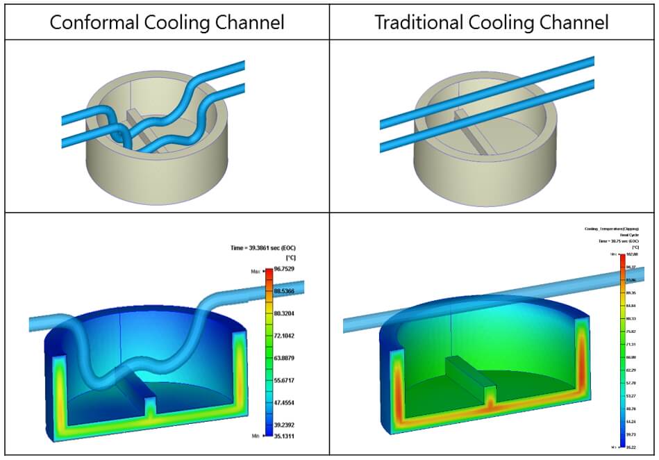
Step 4. Analysis Results and Conformal Cooling Channel effect
Through the conformal cooling channel design that closely follows the product contour, a more uniform temperature can be achieved, resulting in improved heat accumulation.
(Again, as mentioned previously, the cases here are for the purpose of demonstration, the actual design should consider more about tooling processability)
Â
Induction Heat Treatment
Induction heat treatment system is an advanced metal material heat treatment process that uses the principle of electromagnetic induction to heat metal materials, changing their microstructure and improving their physical and mechanical properties. This system is widely used in multiple industries such as steel, aviation, automotive, and machinery manufacturing, and plays an irreplaceable role in improving material hardness, wear resistance, toughness, and other aspects.
working principle
The core of induction heat treatment system lies in electromagnetic induction heating. When an alternating current passes through an induction coil, an alternating magnetic field is generated around the coil. Metal workpieces placed near the coil will generate eddy currents, known as induced currents, under the action of this magnetic field. When this current flows inside the workpiece, it generates heat, causing the workpiece to be heated. By controlling the current frequency, power, heating time, and cooling method, it is possible to accurately perform heat treatment on the workpiece, such as surface quenching, tempering, annealing, normalizing, etc.
system composition
A complete induction heat treatment system mainly includes the following parts:
Induction heater: generates an alternating magnetic field to heat the workpiece.
Power supply: Provides electrical support for induction heaters.
Control system: Monitor and adjust various parameters of the heating process to ensure the effectiveness of heat treatment.
Cooling system: used to control the cooling rate of the heated workpiece and complete the heat treatment cycle.
Fixture: Fix the workpiece to the optimal heating position.
Characteristics and advantages
1. Precise control: By precisely adjusting parameters such as current and frequency, precise control of heating depth and temperature can be achieved.
2. Efficient and fast: Induction heating has a fast speed and can heat up to the desired temperature in a very short time, shortening the heat treatment cycle.
3. Energy saving and environmental protection: There is no open flame during the heating process, which saves a lot of energy compared to traditional furnaces, and there are no harmful substance emissions.
4. Local heating: It can heat specific parts of the component to avoid resource waste and deformation caused by overall heating.
Application Cases
Automotive manufacturing: used for surface quenching of components such as gears, connecting rods, crankshafts, etc., to improve their hardness and wear resistance.
Aerospace: Heat treatment of key components such as aircraft landing gear and engine blades to enhance their fatigue resistance.
Mechanical manufacturing: Quenching treatment of cutting tools, molds, etc. to extend their service life.
Oil extraction: Heat treatment of parts such as drill bits and pipeline joints to improve corrosion resistance and mechanical strength.
conclusion
Induction heat treatment systems play an indispensable role in modern industry through their efficient heating capacity and precise control mechanism. With the continuous advancement of technology, induction heat treatment systems are developing towards smarter and more energy-efficient directions, and more application scenarios will be developed in the future.
Induction hardening, heating equipment, quenching equipment,, induction heating
Ningbo Dedao Electronic Technology Co., Ltd , https://www.nbdedao.com