Differential Pressure Flowmeter Error Analysis and Processing
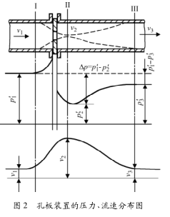
0 Introduction Differential pressure flowmeters are the oldest and most widely used type of flow measurement instrument, and they are also one of the most mature flow measurement instruments in production today. It has the advantages of simple principle, simple equipment, no moving parts, reliable work, long service life, mature application technology, and easy mastery. The fluid filled with the pipe flows through the throttling device in the pipe. Due to the partial contraction of the stream caused by the throttling element, the flow velocity of the fluid in the center of the pipe changes, and the static pressure of the pipe changes accordingly. As the fluid flows through the orifice, local eddy current losses and frictional resistance losses occur. After the fluid stream is fully recovered, the static pressure cannot be restored to its original value. The magnitude of the static pressure difference before and after the throttling element is related to the flow rate. The larger the flow rate, the more pronounced the contraction of the flow bundle and the conversion of the dynamic and static pressure energy, and the greater the pressure difference generated. As long as the static pressure difference before and after the throttling element is measured, the flow rate can be determined. This is the basic principle of the throttling device's flow measurement, as shown in Figure 2. This measurement method is based on the law of conservation of energy and the equation of flow continuity. 2 Causes of measuring errors and their elimination In simple terms, there are three main causes of measurement errors: improper installation or incorrect installation, untimely maintenance or misoperation, changes in process systems or operating conditions.
We have cooperation with the global mainstreamair filter scholars to make more contribution in high efficiency and low resistance melt blown filter products,Activated Carbon Fabric, Spunbond Nonoven Fabric.
About us:
Shenzhen China Textile Filters was established in August,2004. An integrated enterprise, specialized in manufacturing, researching and developing all kinds of filter materials and non-woven fabrics.
We have a group of high-level technicians, advanced equipment of melt-blown fabric, Air Filter Paper, pocket filter media, mini-pleat filter pack, HEPA filter media, etc
After years of development, our products spread all over the world and become the leading production and supplying base of filter materials in the world.
Nonwoven Air Filter Fabric Nonwoven Air Filter Fabric,Meltblown Nonwoven Fabric,Activated Carbon Fabric,Spunbond Nonwoven Fabric Shenzhen China Textile Filters , https://www.ctfiltech.com
The throttling device is usually used with a differential pressure transmitter. Therefore, the measurement error of the differential pressure flowmeter is directly related to the accuracy of the differential pressure transmitter.
At present, many smart differential pressure transmitters have the highest accuracy of 0.075. However, due to various reasons, the measurement errors in actual operation are often large, sometimes reaching 15% to 25%. When conducting economic calculations, this is One problem is particularly acute. Therefore, it is of great practical significance to find out the causes of measurement errors and overcome them as much as possible. Based on years of work experience, the author summarizes some of the common causes of errors in differential pressure flowmeters and methods for eliminating them.
1 The composition and working principle of differential pressure flowmeter The differential pressure flowmeter consists of a standard throttling device (such as a standard orifice plate), an induction line, and a differential pressure transmitter, as shown in Figure 1. Common standard throttling devices include standard orifice throttling devices, nozzle throttling devices, and venturi throttling devices. The standard orifice plate throttling device is the simplest in terms of processing and manufacturing and installation. Through long-term use, standardization of design and installation calculations has been achieved. Standard orifice plate throttling devices are widely used in applications.
The pressure tube leads the differential pressure signal to the differential pressure transmitter. The differential pressure transmitter converts the differential pressure signal into a standard signal output. 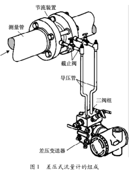
2.1 Installation of Throttling Device The installation of non-standard throttling device meets the requirements. It is an important condition to ensure geometric similarity and dynamics similarity. It is directly related to the measurement accuracy of differential pressure flowmeter. Although the standard throttling device is summed up through a large number of experiments, it can be directly put into production without actual calibration. However, in the installation process, the following irregularities or even incorrect installations are likely to occur, which will lead to measurement errors.
(1) The straight pipe section before and after the throttling device does not meet the requirements. The function of the straight pipe section before and after the throttling device is to ensure the stability of the fluid flow in the pipe. However, due to the frequent turning, bifurcation, convergence, and valve resistance components on the process pipe, The flow beam changes from stable to disturbed, resulting in measurement error. The elimination method is to rationally design the installation position of the throttling device according to the actual situation on the site and in accordance with the requirements of the straight pipelines before and after the construction.
(2) Damage to the upstream and downstream surfaces of the throttling device. Measurement errors are caused due to damage to the upstream and downstream surfaces of the throttling device during transportation or due to careless installation of the throttling device. The elimination method is to improve the technical quality and sense of responsibility of the construction personnel. Before installation, it should be carefully checked. The upstream and downstream surfaces of the throttling device should be inspected and damaged. Replacement of the throttling device should be promptly performed. Care must be taken in the installation process to avoid damaging the throttling device.
(3) The flow direction of the medium in the pipeline and the direction of the throttling device should be correctly identified during installation of the upstream and downstream surfaces of the throttling device. If the directions are inconsistent, the measured value will be low. This is mainly due to the carelessness of construction workers. The elimination method is the same as above.
(4) The installation of different throttling devices with reversed positions is usually especially prone to occur during the commissioning phase. During the commissioning phase, almost all process pipelines require multiple purges, and the throttling devices may be frequently dismantled; if throttling devices are the same size , you will get it wrong by not paying attention. The hydrogen production equipment FE-800 and FE-801 of a company had been installed in reverse, and the errors were significant when they were put into use. The transmitter and the pressure-conducting pipeline were all normal, and they later used a parking opportunity to disassemble the orifice plate. Under the treatment, the two throttling devices were found to have the same serial number and number, and they were normal after the exchange. The elimination method is also the same as mentioned in the above two items.
(5) The throttling body does not install the throttling element as required. There are many standards in the installation process. For example, the throttling body should be perpendicular to the axis of the pipe, and the deviation can not exceed 1°; the throttling element should be connected to the pipe and the clamp (when adopted). Coaxial and so on.
Only in accordance with the installation requirements of the throttle can ensure the accuracy of measurement when used, if not, the measurement is not accurate. The elimination method is the same as above.
(6) Wrong use of spacers Whether it is the gasket between the ring chamber and the flange or between the ring chamber and the orifice plate, the inner diameter size is preferably smaller than the inside diameter of the pipe 2 to 3 mm to prevent the gasket from protruding into the pipe and affecting the flow of the medium. status. The elimination method is to use a suitable size gasket and ensure that the center of the installation is aligned.
2.2 Incorrect installation of pressure guiding pipeline The main purpose of installing the pressure guiding pipeline is to transmit pressure. If the installation is not standardized, it will cause additional errors on the positive and negative pressure sides, resulting in measurement errors. There are usually several reasons.
(1) The pressure guiding pipeline is too short or too long. According to the general technical regulations, the pressure guiding pipeline should be between 3 and 50 m. When it is too short, the measurement fluctuation is large. If it is too long, the measurement lags; and when measuring the liquid, the level should be guaranteed. The pipeline should have a slope of 1:12 to ensure that the pipeline is filled with liquid to avoid measurement errors. However, it tends to conflict with this provision under horizontal and vertical aesthetic installation conditions. The elimination method is to guarantee construction according to technical regulations and design.
(2) When the steam flow is measured, the pressure pickup of the condensate tank is different. This situation also causes additional additional errors in the measurement. The elimination method is to properly install the condensing tank and ensure that the pressure-taking end is of equal height.
(3) Inconsistent heat tracing or too close to the heat source leads to vaporization or density change of the medium in the pressure guiding tube in the north. In winter, some pressure guiding tubes need to be kept warm. If this occurs, the vaporization or density of the medium in the pressure guiding tube will change. , Positive and negative side pressure guiding tubes inconsistent pressure to produce additional errors in the measurement. This happened to a company's hydrogen production equipment. Flow meter FT-204 always indicated normal when no heat tracing was sent. However, after sending heating in winter, the indicator often showed negative values. When the problem was found, the heat tracing pipeline was found. Being too close to the positive pressure tube causes vaporization of the condensate on the positive pressure side. The elimination method is to properly install heat tracing and reasonably select the location of the pressure guiding tube.
2.3 Differential Pressure Transmitter Installation is not standardized Differential pressure transmitter installation environment is too bad, such as vibration, dust or strong corrosive media. The elimination method is to select a suitable location to install the transmitter according to the relevant technical regulations. If it is a special case that must be installed in this environment, the protection measures should be added according to the actual situation on the site, such as adding protection boxes or fixing brackets.
2.4 Inadequate maintenance or misoperation In order to ensure the stable operation of the flowmeter over a long period of time, various measurements are accurately performed. This requires the relevant instrument personnel to maintain it meticulously. Otherwise, the measurement error will be caused because the maintenance is not timely or is misoperation.
(1) When the throttling device is subjected to corrosion and wear of the process medium for a long time, the method of deformation elimination is to dismantle and inspect periodically, and it is found that the deformation should be promptly replaced.
(2) Scale formation on the internal surface of the throttling device, which results in a change in the flow area that is eliminated, is to dismantle and inspect periodically, and it is found that scaling should be promptly cleaned or replaced.
(3) Pressure-plugging or leakage of the pressure-conducting pipe, and blocking or leakage of the three-valve block. Elimination method: On-time inspection, if any problem is found, it shall be dealt with promptly. If leakage occurs, use tools to fasten it. If it is blocked, then it shall be cleaned and drained. Hand-press the pump or other tools to clear it. Ensure the normal delivery of pressure.
(4) The spacer fluid or condensate is lost due to misoperation, resulting in additional errors. The specific elimination method is as follows: For the three valve groups in operation, strictly follow the following two principles: First, the spacer fluid in the pressure tube cannot be The condensate is lost due to misoperation; second, the measuring capsule cannot be pressed or heated in one direction.
(5) The transmitter's zero drift elimination method is to periodically calibrate the zero and span of the transmitter.
2.5 The change of process system or working condition This problem will not appear in general, but when it actually occurs, it may cause considerable measurement error. E.g:
(1) The temperature, pressure, density, viscosity, and other parameters of the medium in the process are different from those in the design. This results in an error between the resulting flow and the actual flow. The elimination method is to carefully verify the design data and related parameters and revise it according to the actual situation to ensure the accuracy of the measurement.
(2) Due to the system modification, the flow value exceeds the original design upper limit, or the state of the medium in the pipeline is changed, causing measurement error. Elimination method: According to the actual situation after the system transformation, modify the process compensation parameters again to meet the requirements of the process measurement accuracy.
To sum up, the differential pressure flowmeter will cause measurement error during use. The following steps can be used to find out the cause of the measurement error of the differential pressure flowmeter and eliminate: 1 For the flowmeter just used for construction, the measurement error is caused by Most of the reasons are due to improper installation or improper installation. 2 For long-term flowmeters, the measurement error is caused by maintenance or misoperation. 3 The measurement error after the technical change is mostly system or process. For reasons.